
Rolling resistance is the force necessary to maintain the equipment at a constant speed.
This force is inversely proportional to wheel diameter and depends on the type of bearing. It also depends upon the surface conditions and load.
MOTIVE POWER
All F.I.R. casters and wheels are specifically manufactured for manual propulsion. Please refer to the manufacturer for wheels and casters required for continuous applications or powered propulsion.
SPEED
F.I.R. casters and wheels nominal load capacities relate to a maximum speed of 4 Km/h ( 1,1 m/s ) – 2,49 mph (1,2 yds/s)
LOAD CAPACITY
To calculate the load capacity of a single caster please use the formula:
4 Wheels equipment
Load = (Equipment weight + solid load) / 3
Load = (Equipment weight + liquid load) / 2
The 4 wheels may not always touch the floor e.g. if the load is not equally distributed or the floor is not even.
For this reason the denominator is 3 or 2. Please apply to our technical staff in relation to load requirements close to the maximum carrying capacities.
TEST CONDITION
Load capacities and tests are determined according to the ISO 22884, UNI EN 12527, UNI EN 12532 Standards. They refer to use under normal conditions:
1) TEST LOAD = nominal load
2) TEST SPEED = 4Km/h (50 m/h – 2,49 mph ±55 ydsIh
3) TEST TEMPERATURE = +15°C ± +28°C – 59°F ± 82,4°F
4) SURFACE in good conditions, hard and solid, with obstacles having the following characteristics: height equal to 5% of wheel diameter in the case of soft tread (up to 90 Shore A); equal to 2.5% of wheel diameter, in the case of hard tread (beyond 90 Shore A).
5) CYCLE: sequence of cycles each 3 minutes maximum, included a maximum pause time of 1 minute.
ENVIRONMENT CONDITION
F.I.R. casters and wheels are manufactured in controlled production processes using the highest quality materials. The following standard conditions are considered as “normal working conditions”:
– temperature range: +5°C to +30°C +41°F to +86° F
– relative humidity: 40% to 80%
– no direct sunlight exposing
– no aggressive physical or chemical agents
STORAGE
F.I.R. recommends that products are stored in a ventilated environment, with temperature between -10°C -50°F and +30°C – +86°F, without high humidity and protected from dust. Do not store for long periods of time, and protect from direct sunlight.
BRACKET AND WHEEL LUBRICATION
Although F.I.R. casters and wheels are maintenance-free, we recommend that the lubrication be checked periodically. A few drops of machine oil may be used to prevent damage when casters are used in severe conditions.
SPECIAL APPLICATION AND/OR ENVIRONMENT
In order to prevent damage and to provide the appropiate caster and wheel in any application, F.I.R. recommends that contact the technical department for information on material resistance and with regard to guy special requirements you may have.
Never use the locking devices to reduce speed during normal work and never use them on gradients in excess of 3%. These conditions apply to all equipment with at least 2 casters fitted with locking devices in contact with the floor.
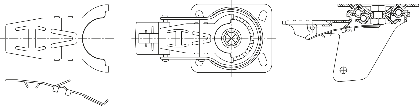
TOTAL LOCK BRAKE
F.I.R. brackets can be supplied with a front or rear total lock brake. This simultaneously locks rolling of the wheel and swivelling of the brackets. The pedal is guaranteed to work in all conditions without locking even in the most adverse environments. Locking and unlocking are very easy and safe. Front and rear total lock brakes are recommended in the following circumstances:
– Front braked brackets: these should be fitted under trolleys which will normally be pushed.
– Rear braked brackets: these should be fitted under trolleys which will normally be pulled.
Total front/rear lock brakes should never be used to reduce the speed of the equipment, but are designed and fitted to hold the position of the trolley once stopped.
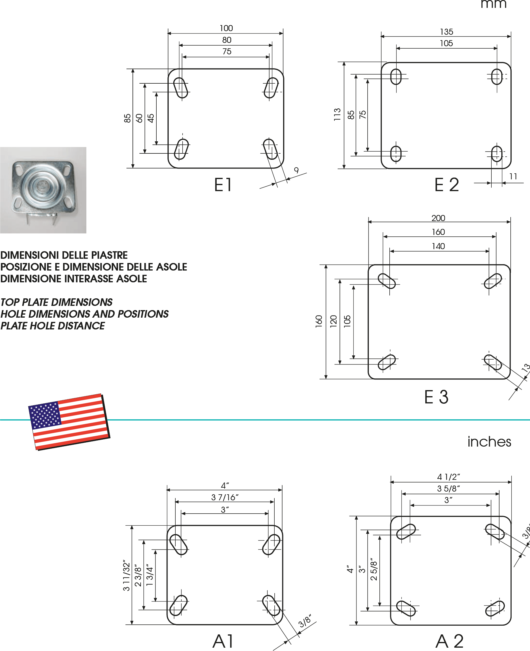
FITTING BRACKET TO EQUIPMENT
We guarantee the performance and the life of our wheels and casters, in line with the product warranty, providing the following conditions are fulfilled:
– the wheel must be fitted into the correct fork using the original axles, bolts and nuts of the correct dimensions
– verification of free rotation of the wheel after fitting
– the top plate caster must be fitted with bolts, nuts and washers of the correct size and quantities indicated by the manufacturer.
– solid stem casters must be fitted into tubular structures with tight tolerance.
– mounting plane surface of bolt hole or threated casters must adhere perfectly to the mounting plane of the equipment.
– bolt hole casters must be fitted using a bolt as recommended by the manufacturer.
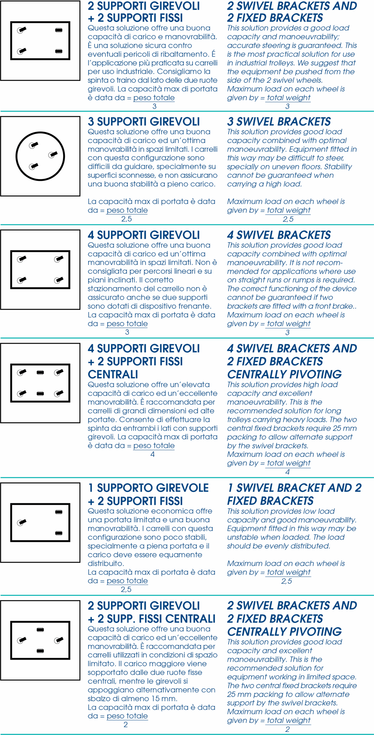
BRACKETS COMBINATIONS
ADDITIONAL STANDARDS
F.I.R. wheels and brackets are manufactured according to the following ISO:
– ISO 22877 – UNI EN 12526
– ISO 22878 – UNI EN 12527
– ISO 22881 – UNI EN 12530
– ISO 22883 – UNI EN 12532
– ISO 22884 – UNI EN 12533
 F.I.R. products are manufactured in compliance with European Directive 2000/53/CE on end-of-life vehicles and European Directive EU 2002/95/CE (RoHS) “Restriction of the use of certain hazardous substances in electrical and electronic equipment” and with regulation REACH (EC) 1907/2006 and following extensions, including SVHC 2022.
 F.I.R. for the environment: F.I.R. combines quality, innovation and respect for the environment. To this end, we have identified those products that may be recycled or regenerated. We strongly encourage use of these products.